![[Warpspeed]](/home.gif)
![[Warpspeed]](/home.gif)
The disk editor (DiskEdit.Exe) comes with a number of modules which allow you to edit disks, both logical and physical, both local and remote, in a variety of ways.
DiskEdit itself only manages the higher level functions. The real editing functionality is contained within the DE*.DLL's themselves. Each DE DLL has a variety of editing modes. Not every DLL supports every editing mode. The available editing modes and the DLL's which support them are as follows:
Edit Mode                   DISPLAY     PHYS    RAW     HPFS    FAT     PIPE
Edit Partition Table        PART TABL   YES     YES     YES     YES     YES
Edit Boot Sector            BOOT SECT           YES     YES     YES     YES
Edit FAT                    FAT                                 YES
Edit Directory              DIR                                 YES
Edit Raw                    RAW         YES     YES     YES     YES     YES
Edit Super Block            SUPER BLK                   YES
Edit Spare Block            SPARE BLK                   YES
Edit Bitmap                 BITMAP                      YES
Edit Directory Bitmap       DIR BITMP                   YES
Edit DIRBLK                 DIRBLK                      YES
Edit FNODE                  FNODE                       YES
Edit ALSEC                  ALSEC                       YES
Edit Code Page Information  CODE PG I                   YES
Edit Code Page              CODE PG                     YES
Edit Bad Block List         BAD BLK L                   YES
Edit Hot Fix List           HOT FIX L                   YES
Edit Bitmap List            BITMAP L                    YES
The Partition Table editing mode allows you to edit the partition table for the selected drive. It is only available when you are editing the very first sector on a hard disk.
When this editing mode is active you will see a window similar to the following:

As you select each column to edit you will be given a help message below the editing window.
The ten columns are:
Column One - Partition Status
This value indicates the current partition status. It is a hexadecimal number. A value of 00 indicates that the partition is not bootable. A value of 80 indicates that the partition is bootable.
Column Two - Partition Type
This value defines the type of the partition. It is a hexadecimal number. The following table lists some of the values which you may find. It is by no means exhaustive.
Column Three - Beginning Cylinder
This value is the cylinder which marks the beginning of the partition.
Column Four - Beginning Head
This value is the head which marks the beginning of the partition.
Column Five - Beginning Sector
This value is the sector which marks the beginning of the partition.
Column Six - Ending Cylinder
This value is the ending cylinder of the partition.
Column Seven - Ending Head
This value is the ending head of the partition.
Column Eight - Ending Sector
This value is the ending sector of the partition.
Column Nine - Partition Offset
This value is the offset in sectors to the beginning of the partition relative to the beginning of this logical drive.
Column Ten - Partition Size
This is the size of the partition in sectors. Each sector is generally 512 bytes long.
The Boot Sector editing mode allows you to edit the boot sector for the selected drive. The Bios Parameter Block (BPB) is contained in the boot sector. It is this information which an operating system reads to determine the configuration of the disk. It is only available when you are editing the very first sector of a floppy disk (typically cylinder 0, head 1, sector 0 of a hard disk).
See also: DI.
The fields which are defined are:
.JMP
These three bytes are machine code instructions which are a jump to the boot code for this disk. This field is a hexadecimal string.
.OEM
These 8 bytes are reserved for the Original Equipment Manufacturer. This field is an ASCII string.
.usBytesPerSector
Sectors are the smallest amount of data which a disk can either read or write. It is determined when the disk is physically formatted. It is usually 512, but it can be 128, 256, 1024 or 2048 as well. This field is a decimal number.
.bSectorsPerCluster
OS/2 and DOS allocate sectors in groups called "Clusters". This is the minimum number of disk sectors which DOS or OS/2 can allocate to a file. This value varies. It depends on the size and type of media. This field is a decimal number.
.usReservedSectors
This is the number of sectors reserved for use by the operating system. This field is a decimal number.
.cFATs
The File Allocation Table (FAT) file system uses tables to save information about where files reside. To assist in maintaining file system integrity more than one copy may be kept. The default is 2. This field is a decimal number.
.cRootEntries
The FAT file system requires a fixed space to be reserved for the root directory. The size of this space is determined when the disk is formatted. The value varies as it depends on the size and type of media. This field is a decimal number.
.cSectors
This specifies the number of sectors available on the disk. This value is only valid for partitions of less than 32Mb in size. This field is a decimal number.
See also: .cLargeSectors.
.bMedia
Specifies a hexadecimal number which lists the type of media in the disk drive. This field is a hexadecimal number. Some common values are:
.usSectorsPerFAT
Specifies the number of sectors occupied by each FAT in the FAT file system. This field is a decimal number.
.usSectorsPerTrack
Each track is divided up into a number of sectors. This is dependent on the disk drive itself. This field is a decimal number.
.cHeads
Specifies the number of heads (or sides) of the logical disk. This field is a decimal number.
.cHiddenSectors
Under FAT file systems this specifies the number of sectors reserved for system use. This field is a decimal number.
.cLargeSectors
This is the number of sectors available on a large partition. A large partition is > 32Mb in size. This field is a decimal number.
See also: .cSectors.
.bDriveNo
This is the drive number. The drive number is used internally by DOS. This field is a decimal number.
.bReserved
Reserved. This field is a decimal number.
.bExtendedSig
This value, if it is 41 (for FAT) or 40 (for HPFS), specifies that this is an extended boot record. An extended boot record has the .ulVolID, .bVolLabel and .bVolType fields in it. This field is a hexadecimal number.
.ulVolID
This is the 32 bit volume ID for this disk. This field is a hexadecimal number.
.bVolLabel
This is the 11 character Volume Label. It is set when the disk is formatted. This field is an ASCII string.
.bVolType
These 8 characters specify the volume (or file system) type. This field is an ASCII string.
The FAT editing mode enables you to edit the File Allocation Table of a FAT disk. It is this table which specifies the actual disk layout of files on a FAT disk. The FAT is a simple chain of numbers. Each number representing a cluster of data. We follow this chain until we reach the end of the chain - which is marked as <EOF>. The other values of note in the FAT are zero (0), which means that the specified cluster is free or unused and BAD which indicates that the particular cluster is unsuitable for use.
The following paragraph describes how the FAT works. A file must have a directory entry in either the root directory or a sub directory cluster. A sub directory is simply a special file (allocated and used like any other) except that the file information in the file is actually a set of directory entries. Each of these directory entries has multiple fields in it. One of which is the starting cluster. If the file size is non-zero, then the starting cluster number is the first cluster of data for that file. The next cluster is represented in the FAT. Take the example below: If a file has a starting cluster of two (2), then the file only contains one cluster's worth of data. The chain ends at cluster 2, as indicated by the EOF. If the starting cluster of a file is nine (9), then the file's data is contained in clusters, 9, 10, 11 all the way through to cluster number 93.
Note : The F12 key may be used at any time to jump to the Current Cluster - as displayed in the top right hand corner of the window.
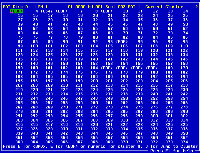
You may use the arrow keys to move around the FAT to edit or change values. The FAT can be very large. On a 2Gb disk there are 65,506 clusters. This can make scrolling though them very difficult. To ease this situation, you can press the J key and you will be prompted with this dialog box:

Simply enter the number that you wish to go to and you will be taken there.
Once you have finished making your changes, you will be prompted to save them. At this point you will be presented with this dialog box:
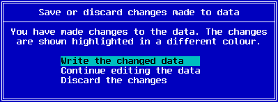
Once you have chosen to write your changes back to disk you will be prompted with another dialog box. Generally there are two copies of the FAT for data redundancy purposes. It is important to keep them both the same. Thus at this point you are prompted to make changes to both or just one of them.

The Edit Directory mode allows you to edit FAT directories in their native format. The following columns are available for editing.
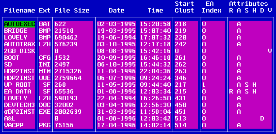
FileName
This is the filename. It is 8 characters wide.
Ext
This is the filename's extension. It is 3 characters wide.
File Size
This is the size of the file in bytes.
Date
This is the date (in Day-Month-Year format) on which the file was last modified.
Time
This is the time (in HH:MM:TwoSec format) on which the file was last modified. The TwoSec field is the time to the nearest two seconds.
Start Clust
This is the starting cluster for the file's data.
EA Index
This is the Extended Attribute index into the "EA DATA . SF" file (the Extended Attribute holding file for FAT partitions).
Attributes
This column has the following sub headings:
Note : The F12 key can be used to jump to the Start Cluster of the currently selected directory entry.
The edit Raw Hexadecimal mode is provided across all of the DE DLL's. This is the default editing mode. It allows you to edit data in both hexadecimal and ASCII.
The edit Super Block function allows you to edit the Super Block of HPFS disks in their native format. The fields which define the SUPERB structure are as follows:
.sig1
This is the first signature value for the Super Block. It should be F995E849.
.sig2
This is the second signature value for the Super Block. It should be FA53E9C5.
.bVersion
This is the version number of the HPFS File System structures. It is normally 2.
.bFuncVersion
This is the functional version number. This is the oldest version of the file system which can understand this disk. It is normally 2.
.usDummy
This is a dummy field used to align everything to a 32 bit boundary.
.lsnRootFNode
This is the Logical Sector Number of the root directory FNODE.
.culSectsOnVol
This is the total number of sectors on the volume.
.culNumBadSects
This is the number of bad sectors on the volume.
.rspBitMapIndBlk.lsnMain
This is the Logical Sector Number of the starting sector of the Bitmap lists.
.rspBitMapIndBlk.lsnSpare
This is unused.
.rspBadBlkList.lsnMain
This is the Logcal Sector Number of the starting sector of the Bad Block lists.
.rspBadBlkList.lsnSpare
This is unused.
.datLastChkdsk
This is the date and time of when CHKDSK /F was last run.
.datLastOptimize
This is the date and time of the last disk optimise.
.clsnDirBlkBand
This is the number of sectors in the DIRBLK band.
.lsnFirstDirBlk
This is the Logical Sector Number of the first 2 KByte block in the DIRBLK band.
.lsnLastDirBlk
This is the Logical Sector Number of the last 2 KByte block in the DIRBLK band.
.lsnDirBlkMap
This is the first sector of the DIRBLK bitmap.
.lsnSidTab
This is the Logical Sector Number of a run of 8 sectors which are used to hold Access Control Information (ACL). In normal HPFS these sectors are reserved and unused. They are only used in HPFS386.
The edit Spare Block function allows you to edit the Spare Block of HPFS disks in their native format. The fields which define the SPAREB structure are defined as follows:
.sig1
This is the first signature value for the Spare Block. It should be F9911849.
.sig2
This is the second signature value for the Spare Block. It should be FA5229C5.
.bFlag
This is the partition status flag. It is bit mapped as follows:
Status Values:
.lsnHotFix
This is the Logical Sector Number of the hot fix mapping table.
.culHotFixes
This is the number of entries in the hot fix table which are in use.
.culMaxHotFixes
This is the maximum number of Logical Sectors in the hot fix mapping table. (ie. the maximum number of sectors which can be hot fixed).
.cdbSpares
This is the number of spare DIRBLKs which are free.
.cdbMaxSpare
This is the maximum number of spare DIRBLKs. It is the number of entries in the alsnSpareDirBlks[] array which are valid.
.lsnCPInfo
This is the Logical Sector Number of the first code page information sector.
.culCP
This is the total number of code pages used on this volume.
.aulExtra[0]
Under normal HPFS this is unused. Under HPFS386 and LAN Server Version 4, this is the 32 bit CRC of the Super Block. If it does not match the value calculated by CHKDSK then CHKDSK /F is run at boot up.
.aulExtra[1]
Under normal HPFS this is unused. Under HPFS386 and LAN Server Version 4, this is the 32 bit CRC of the Spare Block. If it does not match the value calculated by CHKDSK then CHKDSK /F is run at boot up.
.aulExtra[2-16]
These values are unused and reserved for future expansion.
.alsnSpareDirBlks[0-100]
These are the Logical Sector Numbers of a spare DIRBLK.
Note : Only the first SPAREB.cdbMaxSpare entries are valid.
The edit Bitmap mode allows you to edit the sector allocation of HPFS disks. Using this mode you can mark sectors as either being used or free for use.
To use this mode you must currently be editing the FIRST sector of the four sector bitmap block. Use HPFSInfo -m to determine the bitmap sectors.
When you are using this mode you will see something similar to:
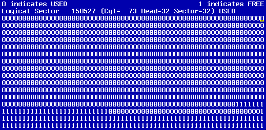
Using the arrow keys, you may move the cursor to the desired sector and press "0" to mark that sector as USED, or "1" to mark that sector as FREE.
This edit mode will automatically scroll the data displayed as all four bitmap sectors are edited at the same time. Normally, the disk editor only operates on a single sector at a time.
The edit Directory Bitmap mode allows you to edit the sector allocation of HPFS disks for the directory band. This is similar to the Edit Bitmap mode, except that with Directory Bitmaps, each bit represents the usage of the four sectors of a DIRBLK. With a normal Bitmap, each bit represents the usage of a single sector. Using this mode you can mark sectors as either being used or free for use.
To use this mode you must currently be editing the FIRST sector of the directory bitmap block. Use HPFSInfo to determine the directory bitmap sector.
The display of the edit Directory Bitmap is very similar to the edit Bitmap mode. Whilst editing the Directory Bitmap block you will see something similar to:
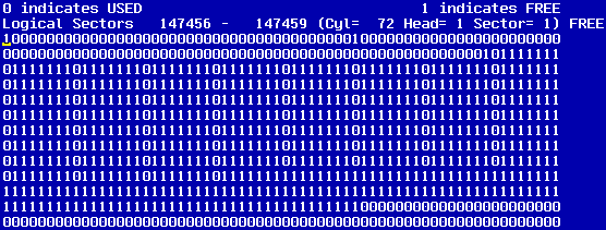
The edit DirBlk mode enables you to edit HPFS Directory Blocks. Each DIRBLK is four sectors long. To edit a DIRBLK, you must be currently editing the first sector of the DIRBLK.
A DIRBLK consists of a small header followed by a variable number of DIRENTs (Directory Entries). Each DIRENT contains the full directory information for that item.
The DIRBLK header fields are as follows.
.sig
This is the signature of the DIRBLK. It should be 77E40AAE.
.offulFirstFree
This is the offset within this DIRBLK to the first free byte.
.culChange
The low bit indicates if this is the topmost DIRBLK in the BTree.
.lsnParent
This is the Logical Sector Number of the parent DIRBLK or, if this is the topmost DIRBLK, then it is the sector number of this directory's FNODE.
.lsnThisDir
This is the Logical Sector Number of this DIRBLK.
The DIRENT fields are as follows:
.cchThisEntry
This is the length of this DIRENT entry. It includes any free space which is on the end of the entry.
The size of a DIRENT is always a multiple of four to force double word alignment. The name is variable length and the DIRENT.BTree down pointer, if present, is the last double word in the entry. Thus there may be padding bytes after the name and before the BTree down pointer. Access Control List information may be stored after the name but before the DIRENT.BTree field. Thus, in order to access the BTree pointer, HPFS must locate it from the end of the DIRENT, rather than from the beginning, based on the name length.
.fFlags
These are the flags for this DIRENT.
.fFlags Values:
.fAttr
These are the file attributes for this DIRENT.
.fAttr Values:
.lsnFNode
This is the Logical Sector Number for the FNODE of this entry.
.timLastMod
This is the time and date at which the file was last modified.
.cchFSize
This is the file size.
.timLastAccess
This is the time and date on which the file was last accessed.
.timCreate
This is the time and date on which the file was created.
.ulEALen
This is the number of bytes of Extended Attributes associated with this entry.
.fFlex
This is the "flex" area for this DIRENT. The low three bits are the number of ACL's present. The upper bits are reserved.
.bCodePage
This is the code page index on the volume. It is 7 bits wide. The 8th bit indicates that there are DBC'S present.
.cchName
This is the length of the file name.
.bName
This is the name of the file.
Note : EXTREME CAUTION should be used when editing this entry. HPFS sorts the DIRENT entries within each DIRBLK based on the file name. Changing the file name may have disastrous effects.
.bTree
This is a BTree pointer to a descendent DIRBLK.
The edit FNODE mode allows you to edit FNodes in their native format. The fields which define a FNODE are as follows:
.sig
This is the signature for the FNODE. It should be F7E40AAE.
.ulSRHist
This is the Sequential Read History. It is currently unused.
.ulFRHist
This is the Fast Read History. It is currently unused.
.achName[0] (name length)
This is the length of the file name.
.achName[1] (name itself)
This is the file name itself.
.lsnContDir
This is the Logical Sector Number of the directory FNODE which contains this file or directory. (ie. the parent FNODE).
.aiACL.sp.cbRun
This is the number of sectors used to describe an external ACL definition. The ACL is too large to fit into the FNODE.
.aiACL.sp.lsn
This is the Logical Sector Number of the external (to the FNODE) ACL sector.
.aiACL.usFNL
This is the length of the FNODE resident ACL information.
.aiACL.bDat
This is non zero if the FNODE.aiACL.sp.lsn is an ALSEC. If it is not, then it is direct data.
.cHistBits
This is the count of history bits. It is currently unused.
.aiEA.sp.cbRun
This is the number of sectors used to describe an external EA data definition. The EA data is too large to fit into the FNODE.
.aiEA.sp.lsn
This is the Logical Sector Number of the external (to the FNODE) EA data sector.
.aiEA.usFNL
This is the length of the FNODE resident EA information.
.aiEA.bDat
This is non zero if the FNODE.aiEA.sp.lsn is an ALSEC. If it is not, then it is direct data.
.bFlag
If the low bit is on, this indicates that this is a directory FNODE. Otherwise this is a file FNODE.
.fst.alb.bFlag
This is the flag byte to describe the B+ tree information.
0x20 Parent is an FNODE
0x80 Following are ALNODE structures.
If the ALNODE bit is not set, then the following are ALLEAF structures.
.fst.alb.bPad
This is used to align to a 32 bit boundary.
.fst.alb.cFree
This is a count of the number of free entries left in the array.
.fst.alb.cUsed
This is a count of the number of entries in the array which are in use.
.fst.alb.oFree
This is the offset to the next free element in the array.
.fst.a.aall[0-7].lsnLog LEAF FNODE
This is the logical sector offset within the file. This number starts at zero.
.fst.a.aall[0-7].csecRun LEAF FNODE
This is the length, in sectors, of the block of data on the disk.
.fst.a.aall[0-7].lsnPhys LEAF FNODE
This is the sector number on the disk of the first sector of the block. If the FNODE corresponds to a directory, then this field is the LSN of the topmost DIRBLK in the BTree.
.fst.a.aaln[0-11].lsnLog NODE FNODE
This is the logical sector offset within the file.
.fst.a.aaln[0-11].lsnPhys NODE FNODE
This is a Logical Sector Number of a sector on disk which contains an array of ALNODES or an array of ALLEAFs (ie. an ALSEC).
.fst.ulVLen
This is the length of valid data within the file.
.ulRefCount
This is the number of "Needed" EA's for this file.
.achUID
This is the User ID. It is currently unused.
.usACLBase
This is the offset into the FNODE of the first ACL entry (if present) or EA.
.abSpare
This is currently unused.
The edit ALSEC mode enables you to edit an ALSEC sector in its native format. The .alb.bFlag variable defines whether an ALSEC contain either 40 ALLEAF structures or 60 ALNODE structures. The fields which define an ALSEC are as follows:
.sig
This is the signature for the ALSEC. It should be 37E40AAE.
.lsnSelf
This is the sector of the allocation block itself. This is used for allocating other blocks near the current one.
.lsnRent
This is the Logical Sector Number of the parent of this sector. The ALSEC.alb.bFlag byte indicates if the parent is either a FNODE or another ALSEC.
.alb.bFlag
This is the flag byte to describe the B+ tree information.
If the ALNODE bit is not set, then the following are ALLEAF structures.
.alb.bPad
This is used to align to a 32 bit boundary.
.alb.cFree
This is a count of the number of free entries left in the array.
.alb.cUsed
This is a count of the number of entries in the array which are in use.
.alb.oFree
This is the offset to the next free element in the array.
.a.aall[0-39].lsnLog LEAF ALSEC
This is the logical sector offset within the file. This number starts at zero.
.a.aall[0-39].csecRun LEAF ALSEC
This is the length, in sectors, of the block of data on the disk.
.a.aall[0-39].lsnPhys LEAF ALSEC
This is the sector number on the disk of the first sector of the block. If the FNODE corresponds to a directory, then this field is the LSN of the topmost DIRBLK in the BTree.
.a.aaln[0-59].lsnLog NODE ALSEC
This is the logical sector offset within the file.
.a.aaln[0-59].lsnPhys NODE ALSEC
This is a Logical Sector Number of a sector on disk which contains an array of ALNODES or an array of ALLEAFs (ie. an ALSEC).
.bPad
Twelve bytes of padding to pad it out to a sector. This is unused.
The edit Code Page Information mode allows you to edit code page information sectors in their native format. Each code page information sector has a small header followed by up to 31 CPINFOENTRY structures. The fields which define a CODEPAGEINFOSECTOR are as follows:
.sig
This is the signature of the Code Page Information Sector. It should be 494521F7.
.cCodePage
This is the count of code page information entries which follow in this sector.
.iFirstCP
The volume specific index of the first code page in the array of code page information entries which follow. For this first code page info sector this will be zero, for the next one this will be 31, and so on.
.lsnNext
This is the sector number of the next code page information sector. If there are no additional code page information sectors, then this will be zero.
Each CPINFOENTRY structure is defined as follows:
.CPInfoEnt[0-30].usCountryCode
This is the country code of this character set.
.CPInfoEnt[0-30].usCodePageID
This is the code page for this character set.
.CPInfoEnt[0-30].cksCP
This is the checksum of corresponding code page data entry. The code page data entry appear in a code page data sector pointed by CPINFOENTRY.lsnCPData.
.CPInfoEnt[0-30].lsnCPData
This is the Logical Sector Number of code page data sector which holds the code page data entry for this character set.
Note : A Code Page Data Sector can hold three separate code pages.
.CPInfoEnt[0-30].iCPVol
This is the volume specific index of this character set.
.CPInfoEnt[0-30].cDBCSRange
This is the count of DBCS ranges in this character set.
The edit Code Page mode allows you to edit code page data sectors in their native format. Each code page data sector has a small header followed by up to three CPDATAENTRY structures. The fields which define a CPDATASECTOR are as follows:
.sig
This is the signature for the Code Page Data Sector. It should be 894521F7.
.cCodePage
This is the count of code page data entries in this sector.
.iFirstCP
This is the volume specific character set index of first code page data entry in this sector.
.cksCP[0]
This is the checksum of the first code page data entry contained in this sector.
.cksCP[1]
This is the checksum of the second code page data entry contained in this sector.
.cksCP[2]
This is the checksum of the third code page data entry contained in this sector.
.offCPData[0]
This is the offset of the first code page data entry.
.offCPData[1]
This is the offset of the second code page data entry.
.offCPData[2]
This is the offset of the third code page data entry.
Each CPDATAENTRY is defined as follows:
.CPData[0-2].usCountryCode
This is the country code for this character set.
.CPData[0-2].usCodePageID
This is the code page for this character set.
.CPData[0-2].cDBCSRange
This is the count of the DBCS ranges. This will specify the number of DBCS range pairs in the DBCSRange array.
.CPData[0-2].bCaseMapTable (128-143)
This is the 16 byte mapping table for characters 128 to 143 in this character set.
.CPData[0-2].bCaseMapTable (144-159)
This is the 16 byte mapping table for characters 144 to 159 in this character set.
.CPData[0-2].bCaseMapTable (160-175)
This is the 16 byte mapping table for characters 160 to 175 in this character set.
.CPData[0-2].bCaseMapTable (176-191)
This is the 16 byte mapping table for characters 176 to 191 in this character set.
.CPData[0-2].bCaseMapTable (192-207)
This is the 16 byte mapping table for characters 192 to 207 in this character set.
.CPData[0-2].bCaseMapTable (208-223)
This is the 16 byte mapping table for characters 208 to 223 in this character set.
.CPData[0-2].bCaseMapTable (224-239)
This is the 16 byte mapping table for characters 224 to 239 in this character set.
.CPData[0-2].bCaseMapTable (240-255)
This is the 16 byte mapping table for characters 240 to 255 in this character set.
.CPData[0-2].DBCSRange[0].ucStart
This is the start byte of the DBCS lead byte range.
.CPData[0-2].DBCSRange[0].ucEnd
This is the end byte of the DBCS lead byte range.
The edit Bad Block List mode enables you to edit the bad block list in its native format. The BADBLOCKLIST structure has the following fields:
.lsnNextSector
This is the Logical Sector Number of the next BADBLOCKLIST structure. If it is zero, then there are no more entries.
.lsnBadSector[0-510]
The Logical Sector Number of sectors which have been marked bad.
The edit Hot Fix List mode allows you to edit the dynamic hot fix list in its native format. The length of each array is defined by the SPAREB.culMaxHotFixes item. The HOTFIXLIST structure is defined as follows:
.lsnFrom[]
This is the Logical Sector Number of a sector which has been marked bad dynamically.
.lsnTo[]
This is the Logical Sector Number of a sector which has been reserved to act as a spare when a dynamic hot fix occurs.
.lsnFNode[]
This is the Logical Sector Number of the FNODE of the file or directory that owns the damaged sector.
The edit Bitmap List mode enables you to edit the bitmap lists in their native format. Each BITMAPLIST structure is four sectors long. If the list needs to be greater than four sectors long, it will flow onto the next four contiguous sectors. The list is terminated by a zero entry.
.lsnStartBitmapSector[0-511]
This is the Logical Sector Number of first sector of a bitmap band.